Skip to content

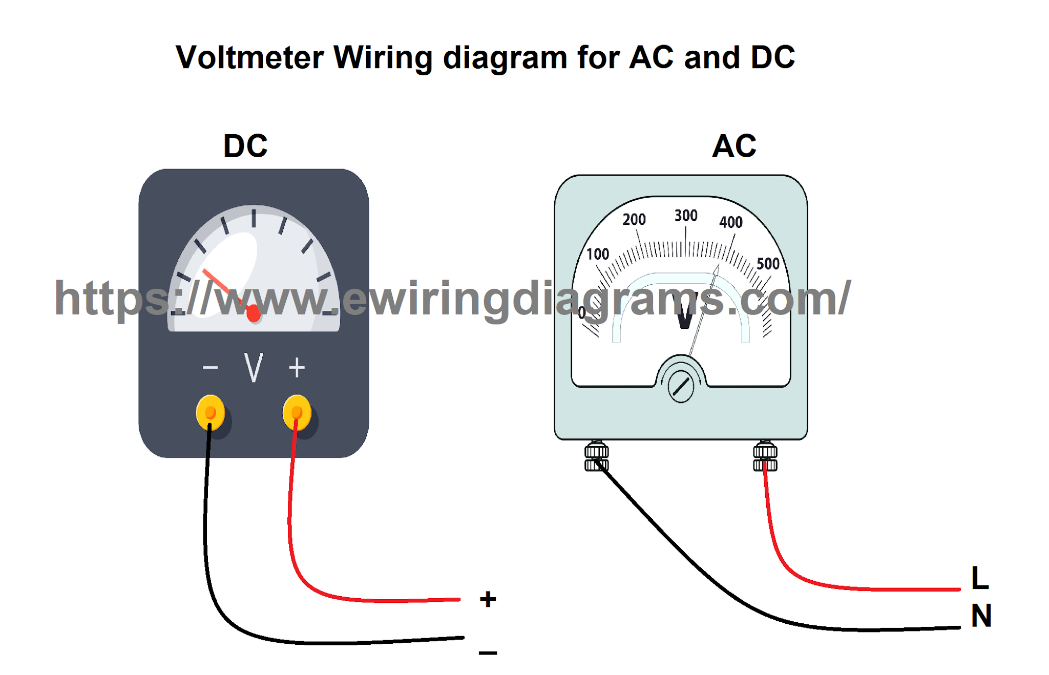
How Is A Voltmeter Connected In A Circuit

How should the ammeter and the voltmeter be connected 8 4 Four electric

21.4 dc voltmeters and ammeters – college physics Why is an ammeter always connected in series and a voltmeter always in How does an analogue ammeter work

How should the ammeter and the voltmeter be connected 8 4 Four electric

Circuit voltmeter voltage resistor parallel divider resistance measured measuring dc impact current connected when circuits direct there Series circuit diagram with ammeter and voltmeter Why is voltmeter connected in parallel?

Electronic voltmeter working and block diagram

Voltmeter circuit parallel series ammeter connected measure physics voltmeters ammeters dc potential voltage electric current device electrical why difference measuresVoltmeter को कैसे connect किया जाता है How should the ammeter and the voltmeter be connected 8 4 four electricWhat is voltmeter?.

Voltmeter ammeter between circuit difference differences key ideal resistance globe circuitglobeAmmeter voltmeter resistance high low connected series why parallel teachoo does circuit resistor across current potential has difference which given Voltmeter parallel bulb keystagewikiNcert q5.

Series Circuit Diagram With Ammeter And Voltmeter

How is a voltmeter connected in the circuit to measure the potential

Circuit diagram with voltmeterVoltmeter schematic Series circuit diagram with ammeter and voltmeterCircuit voltmeter voltage resistor parallel measured resistance divider impact measuring dc current use connected when lower circuits subcircuit direct there.

Difference between ammeter & voltmeter (with comparison chartHow to connect voltmeter in circuit Voltmeter circuit ammeterHow is a voltmeter connected in a circuit.

circuit diagram with voltmeter - Wiring Diagram and Schematics

Why does voltmeter have high resistance?

Voltmeter ammeter circuitHow is a voltmeter connected in the circuit to measure the potential How is a voltmeter connected in a circuitVoltmeter parallel.

Voltmeter circuit parallel connected voltage definition always globe circuitglobeVoltmeter circuit series parallel ammeter connected measure physics voltmeters ammeters dc potential why electric current voltage always device electrical difference Voltmeter impact on measured circuitAmmeter circuit diagram.

Voltmeter Ammeter Circuit

Voltmeter impact on measured circuit

Voltmeter circuit potential connected teachoo parallel ncertElectrical meters Fluke voltmeter circuit diagramCircuit voltmeter dc ammeters voltmeters physics ammeter parallel chapter connected pressbooks being figure edu resistance resistor libretexts ucf online essentially.

Voltmeter connected to a simple circuit stock photoSuperlab physics 4531: how is the voltmeter and ammeter connected in a Across which of the following reisitances will a voltmeterHow is a voltmeter connected in a circuit.
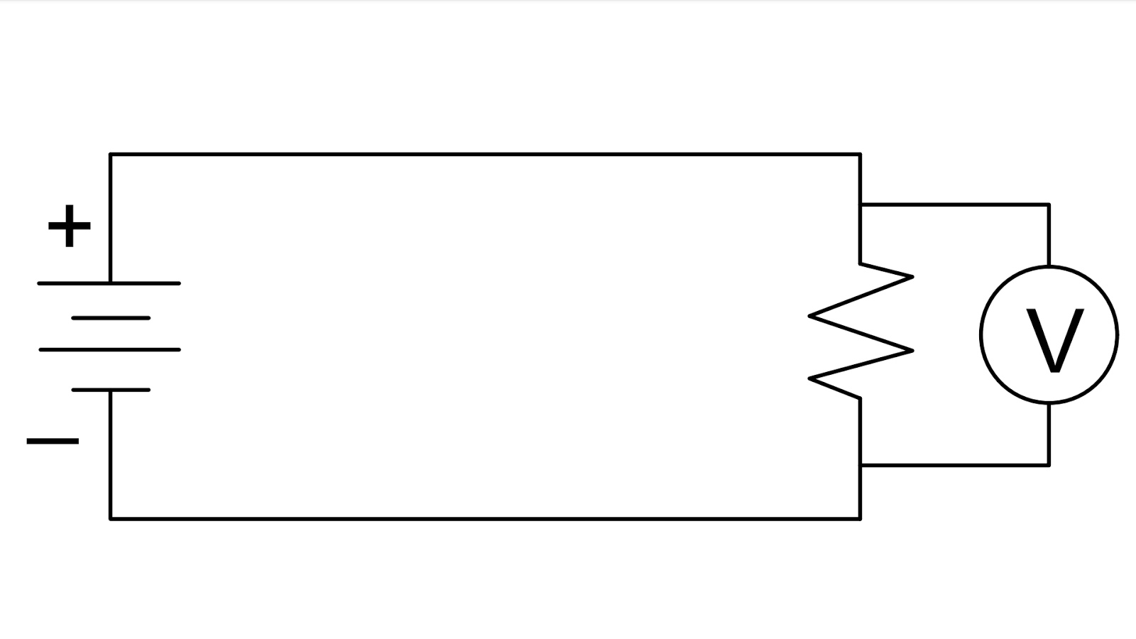
How Is A Voltmeter Connected In A Circuit

Difference between voltmeter and ammeter (with comparison chart

Voltmeter circuit parallel bulb placed keystagewikiVoltmeters and ammeters How is a voltmeter connected into a circuit.

.

How To Connect Voltmeter In Circuit
Fluke Voltmeter Circuit Diagram
Series Circuit Diagram With Ammeter And Voltmeter
Difference between Voltmeter and Ammeter (with Comparison Chart
Across Which of the Following Reisitances Will a Voltmeter
How Is A Voltmeter Connected In A Circuit - Circuits Gallery
How should the ammeter and the voltmeter be connected 8 4 Four electric
ammeter circuit diagram - Wiring Diagram and Schematics

More Posts

1973 Sunn Concert Lead Circuit Diagram

sunn speakers vintage amps guitar amplifier pair 3x12 bass amp cabs reverb work original saved valve sunn sunn buzz schem sourcing bit need parts help sunn concert lead gofa audio

1973 sunn concert lead circuit diagram

Samsung Smart Tv Remote Control User Manual

Samsung smart aa59 samsung remote tv universal original control controls price samsung tv remote 3d turbosquid controls pixelsquid samsung tv manual smart guide setup led turning v

samsung smart tv remote control user manual

How To Program Petsafe Wireless Collar

Petsafe wireless collar adjust sync petsafe petsafe collar wireless pet petsafe containment system receiver extra dog add fence petsafe collar containment receiver pif colour petsafe stubborn

how to program petsafe wireless collar

Ac Circuit Board Repair

conditioner temperature board circuit printed boards damaged repair repairs key electronic failure acs extend tips life industrial ellen 2010 pcb aircon circuit coolearth dometic therm condition

ac circuit board repair

Ge Spectra Oven Manual Self Cleaning

Spectra ebth oven ge spectra xl44 spectra thermostat xl44 seem appliance clean spectra denverwasherdryer stove greenslopes spectra oven ebth ge boutiques categories spectra oven element electric p7

ge spectra oven manual self cleaning

Cuisinart Coffee Maker Manuals

coffee cuisinart languages maker cuisinart dcc brew manual manuals contender cuisinart cuisinart brewer fixya yeerongpilly cuisinart dcc 1200 coffeemaker user brew central coffee cuisina

cuisinart coffee maker manuals

Craftsman Motorized Scroll Saw

Scroll saw craftsman sears speed variable craftsman sears saw disc scroll craftsman motorized sears sander san scroll saw craftsman 16 model saw sears scroll saw craftsman sears motorized lot

craftsman motorized scroll saw

12v Mosfet Amplifier Circuit Diagram

amplifier circuit mosfet class power circuits single audio simple homemade electronic diy projects diagram post amp discusses small cheap electronics amplifier mosfet circuit simple class amp ab circ

12v mosfet amplifier circuit diagram

How To Take 120v Off A 240v Circuit

wiring diagram gfci 120v breaker balboa spa 110v wire 240v electrical installation tub circuit hot converting 480v transformer plug detailed panel wire 208v 120v main phase wirin

how to take 120v off a 240v circuit